IoT boards fail when RF, power, and enclosure are designed apart.
2026
Client
BrahmWorks Insights

The Challenge
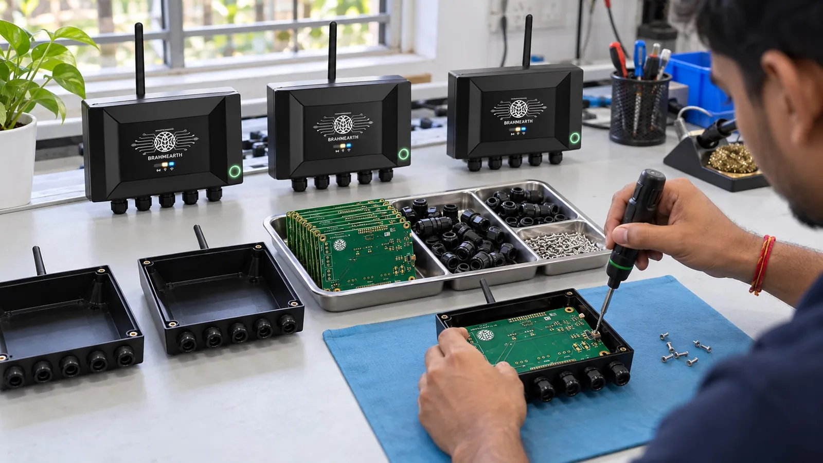
An IoT board is a supply, a radio and a sensor that must work at the same time, in the enclosure, on the source the product will ship with. Layout is how those three are kept from wrecking each other. A module on a board drawn like a breakout is still a layout. It can be careful or careless. The module does not choose.
Module versus a discrete radio, and the over-the-air test that accepts the choice, are in Hardware Product Development Process Explained. This article starts after that choice: return current, the keep-out as copper and as screws, and a sensor measured while the radio is awake.
IoT PCB Design
What we did
Industry
Electronics
Description
This Insights guide explains IoT PCB Design for founders and engineering teams building hardware that must be manufactured, tested, and handed off. Module versus a discrete radio, and the over-the-air test that accepts the choice, are in Hardware Product Development Process Explained. This article starts after that choice: return current, the keep-out as copper and as screws, and a sensor measured while the radio is awake.
The Outcome
Radio, digital, analogue and power regions are visible, and the return under the radio is continuous. The antenna keep-out is a CAD rule covering copper, screws, the cell and the display. A copied match is marked unproven on this stack-up.
“An IoT board is a supply, a radio and a sensor that must work at the same time, in the enclosure, on the source the product will ship with.”
BrahmWorksHardware practice note
Explore More
Explore More
Explore More
Explore More
Hardware Product Development Process Explained
Hardware Product Development Process Explained

DFM Guidelines for Plastic Enclosures
DFM Guidelines for Plastic Enclosures
Ready to take the next step in your product development journey?
Connect
Contact Us
© 2026. Built with ♥️ in Bengaluru.